Antennas - indistinguishable from magic
Work in progress!
Antennas - Black magic?
The Antenna - the single simples electric circuit possible to imagine - just a piece of wire! Still, it's tremendously complicated, handling several different tasks:
- Radiator and/or pickup of electromagnetic radio frequent radiation
- Oscillator circuit
- Transmission line driver/receiver
Although those tasks are related, they aren't always strictly connected. As you'll see here, some are even sometimes in conflict with each other, but sometimes there are workarounds and other tricks.
"Some of them [rules] can be bent. Others can be broken. Understand?"
The goal of this article
I will not tell you anything useful to you building a better antenna, such as giving you formulas telling you how high you need to place it for a certain radiation pattern and so. Instead I aim to help you understand why those formulas look like they do. Most things in this paper are deducted by reasoning, and I will not tell you how things are, but why they are as they are. This way you can figure out the how yourself, if I'm doing my part right. If you are lacking references and sources, I'm doing things wrong - most things here are supposed to be obvious once explained. Please tell me whats parts I've failed at this, if so.
The generic antenna - The Dipole
The Dipole is the mother of all antennas, and most antennas can be explained by explaining The Dipole Antenna. Therefor I'll use it as the generic antenna in this paper. Other antennas, The Whip Antenna (monopole), is basically a Dipole cut in half, and as most other antennas it shares the same basic principles.
The Antenna as an Oscillator circuit
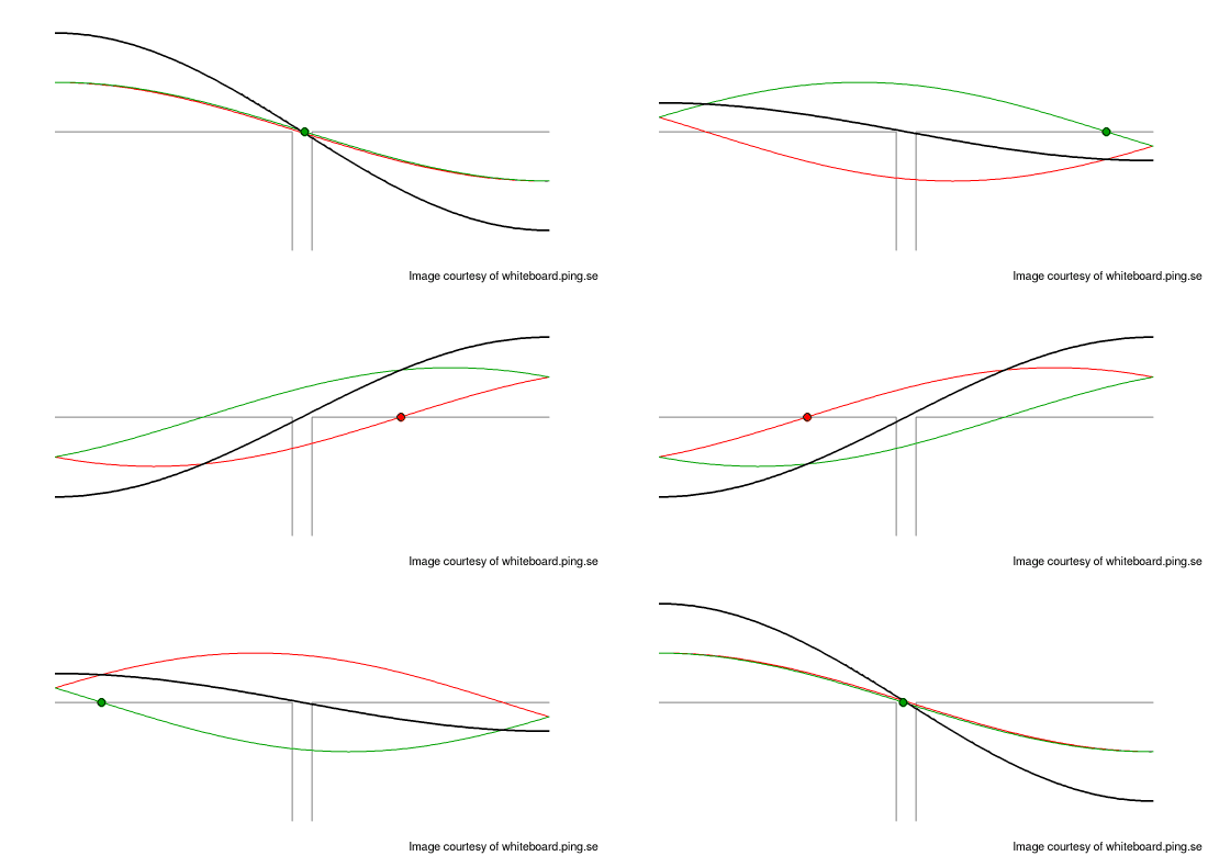
The antenna acts as an oscillator bandpass filter selecting the frequency of interest and filtering away everything else. Lets look at the voltages in the perfect antenna.

Dipole voltage
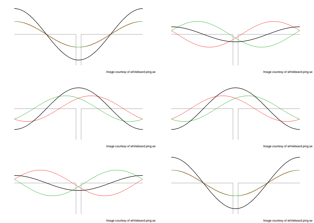
Voltage over the 1/2 length dipole antenna at resonance frequency. Green represents forward wave, Red the reflection, and Black the sum of them both; the resulting resonant standing wave. The dot on the line marks an arbitrary point on the waveform just to make it easier for you to follow the signal reflecting back and forth between the two open ends of the antenna.
The electric signal in the resonant antenna forms a standing wave.
Realize that the antenna in resonance is a standing wave. This is a good thing, and not to be confused with the "VSWR" Voltage Standing Wave Ratio you don't want to have back to your transmitter. At the center of the 1/2 dipole the voltage standing wave in the antenna is constantly close to zero (i.e. have a node). By placing the feeding point here there is no potential to drive the power back to the transmitter, causing a bad standing wave in the feed line, i.e. "High VSWR" (there are other causes of a high VSWR, tough).
Length of the antenna
The idea of an antenna is to receive and/or transmit radio frequent electromagnetic radiation, i.e. radio waves. To do this, the electromagnetic fields of the antenna must oscillate at the same frequency as the radio wave to be able to interact. The electric wave in the antenna therefor must propagate down the antenna wire, reflect, propagate back, ending up at the starting point at the same time the radio wave completes its period. Formulated in wavelength this means, the wavelength of the radio wave in air must equal the wavelength of the electric signal in the antenna wire. But because the wave travels forth plus back in the dipole, it must be half the electric wavelength long, hence half wavelength dipole, or λ/2 dipole.
The electric wavelength in the antenna must be equal to the electromagnetic wavelength in air.
Therefor we need to calculate the different speeds. The wave propagation speed (or velocity factor, if expressed relative c) of a wave in a wire is directly related to the capacity (per length unit) and inductance (per length unit) of the the wire ((LC)-0.5 m/s), and for a wire in air such as an antenna, this turns out to be about 95% to 99% of the speed light, or 0.95-0.99c (this figure may be quite familiar to you if you've built antennas). And the speed of the radio wave in air, is close enough to the speed of light it can be approximated with c.
The inductance and capacitance of a wire such as an antenna isn't constant through all its length, but will differ somewhat at the center compared to the ends. More significant, other stuff close to the antenna wire, such as trees, you, metal thingies etc, may change the capacitance of it quite a lot, changing its velocity factor, making it operate at some other frequency than expected.
Higher harmonics
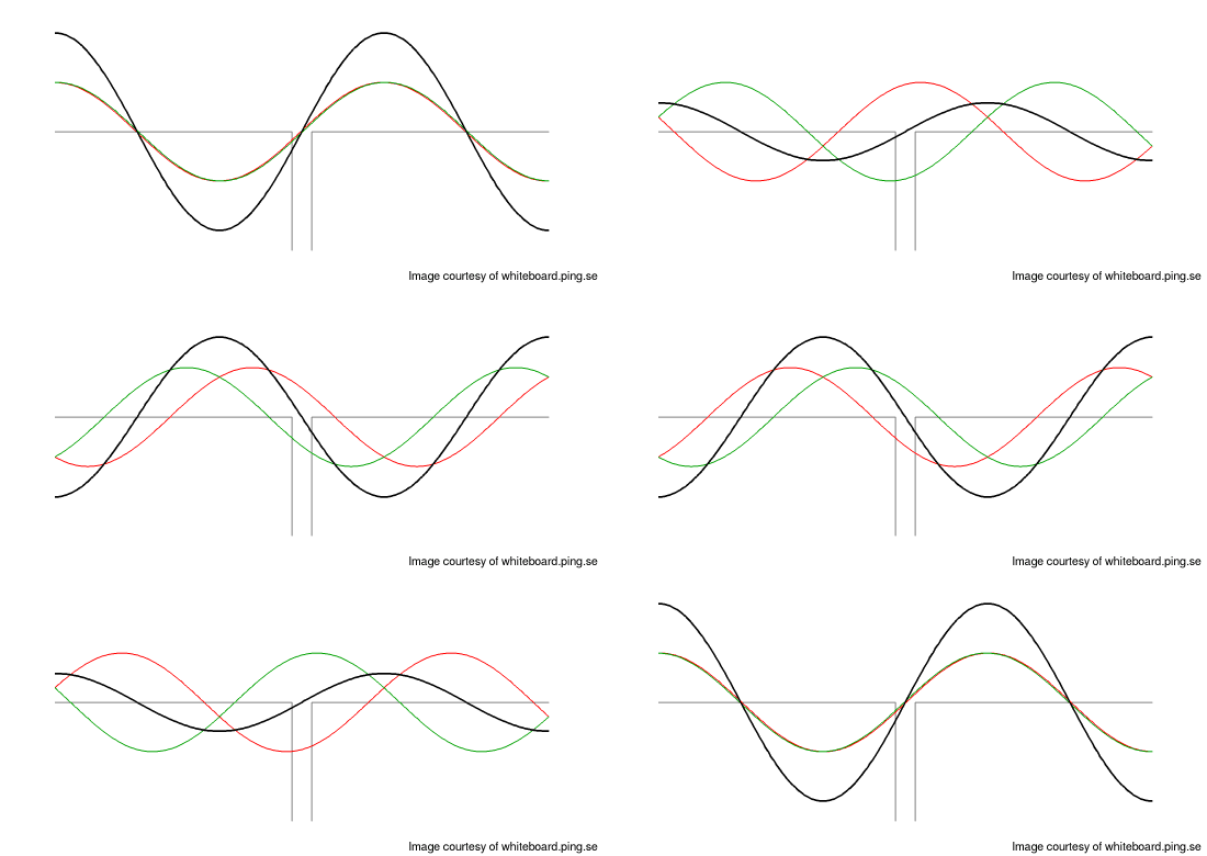
Of course, above is just the fundamental resonance frequency. The dipole will also be resonant at every harmonic (multiple) of it. Lets have a look at twice the frequency.

Second harmonic
This is obvious a standing wave as well. The voltage, Black, standing still with respect to sideways motion. So the antenna is resonant at multiples of the fundamental frequency.
- But there's another problem - do you spot it?
Although this antenna is resonant at two times the fundamental frequency, you won't be able to have any fun with it. Look at the nodes! The zero volt node do no longer occur at the feeding point. Instead you've got a maximum here. Running the antenna at this frequency, and you won't be able to pass any energy into it! Thankfully, because if you could, you would get the VSWR from hell back to your transmitter. *zap* Unless you move the feed point, and then you can't use it at the fundamental. So although resonant, here we fail the "transmission line driver/receiver" feature of the antenna.
This is why the antennas only can be used at odd multiples of the fundamental frequency. Got a dual band radio? 2m and 70cm (144MHz and 432MHz)? Realized that's a difference of precisely three? Believe it's a coincident? :-)
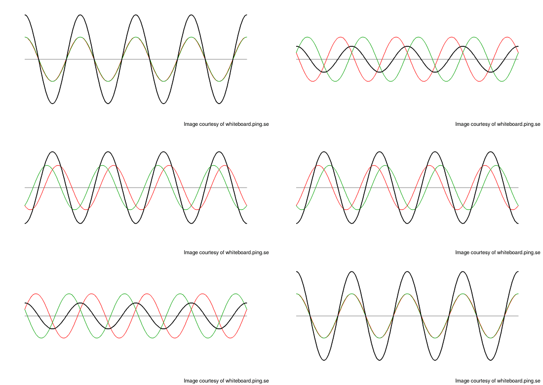
Lets have a look at an odd harmonic. Here's the third harmonic, possible used in your dual band radio running at 70cm, i.e 432MHz (if not using other tricks).

3rd harmonic
Here the zero volt standing wave node is back at the feeding point, and the antenna satisfy both the function as an oscillator as well as a transmission line driver. Also, with one and a half period in each direction, you can better see the electric waves traveling forth and back in the antenna, compared to the other illustrations above.
The Antennas as a Transmission Line Driver/Receiver
The antenna isn't of much use if it can't deliver and/or receive the signal to/from the radio.
The Antenna as an electromagnetic Radiator/Pickup
Terms used
- VSWR - Voltage Standing Wave Ratio. A measurement of an unwanted standing wave caused by energy reflected back from the antenna in the direction to the transmitter.
c- The speed of light in vacuum, about 300 million meters per second.- Feed point - The place on your antenna you supply it with its power. For the dipole, typically at the center.
- Harmonic - A multiple of a fundamental frequency, overtones. First harmonic is the fundamental frequency, tough.
- Fundamental frequency - The lowest frequency of resonance. First harmonic.
- Dipole - If you need to look this up, this paper probably isn't your cup of tea.
- Transmission line - An electric conductor with controlled capacitance (per length unit) and inductance (per length unit) making the wave propagation deterministic (with respect to speed and impedance).
- Standing wave - When two waves meet, they'll sum up. This applies even if the wave meets its own reflection. If the medium length is divisible by the wavelength, the forth-and-back-reflected wave will end up in the same track as to begin with. Even though the wave and its reflections travels forth and back, the sum of them will cancel this movement out, resulting in an amplitude variation but no phase shift. Especially the places where the amplitudes constantly cancel out, the zero crossings will lay still. These are called nodes. If the medium (antenna, coax, guitar string...) isn't dividable by the applied wavelength, the reflections will interfere at random, canceling each other out, leaving only the harmonics of the frequency that are dividable left.

Standing wave
- Resonance - The place where standing wave lives.
About
At present - this page is Work in Progress, so have mercy. :-)
Questions? Criticism? Praise? Other feedback? Send me a mail!
The animated GIFs here are generated using libgd and gcc, the graphs using gnuplot and the illustrations using OpenOffice/LibreOffice Draw. No Mathematica was harmed during the creation of this page.
If this page looks bad, renders incorrect etc, consider upgrading your web browser.
If using images or other material from this web, please credit me by linking back to this page.
/By Mikael Q Kuisma